Description
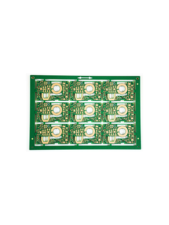
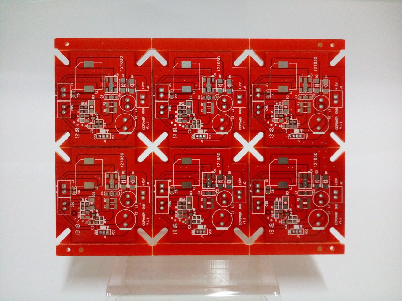
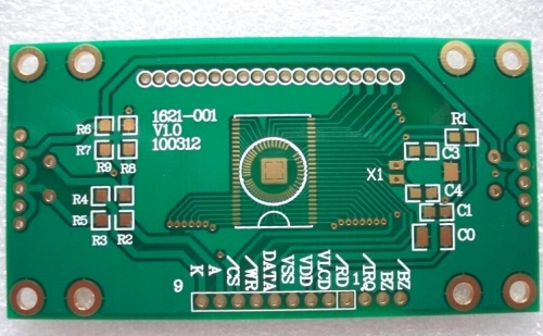
Whether rigid or flexible, the high-frequency printed circuit board provides quicker signal flow rates and then a frequency range of up to 100 GHz. It’s significant to note that a variety of materials are created to function at high-frequency regions. Low levels of thermal expansion, a reduced dissipation factor, and a lower dielectric constant (Dk) are characteristics of HF PCBs. They are frequently utilized in HDI technology.
Materials used for HF circuit boards
To attain the high frequency offered by this type of PCB, special materials are needed. Your design can be supported by a number of substrate materials, which may vary depending on the signal rates needed and the implementation of the circuit board. High-frequency boards have unique requirements for the material used, such as for wireless applications & data rates there in the upper GHz range:
- Adapted permittivity
- Low attenuation, for efficient signal transmission
- Low tolerances for insulation thickness & dielectric constant in homogeneous construction.
Any variations in the Er values of these materials can have an impact on the board’s impedance, which is why special materials are needed to accomplish the high frequency offered by this kind of printed circuit board.
Advantages of PCB high frequency board
1. Fast
The transmission speed is inversely proportional to the square root of the dielectric constant, which means that the smaller the dielectric constant, the faster the transmission speed. This is the advantage of the high-frequency board (high-frequency microwave radio frequency board). It uses special materials to not only ensure the low dielectric constant but also maintain the stability of operation, which is very important for signal transmission.
2. Large degree of controllability
It is widely used in PCB high-frequency boards (high-frequency microwave radio frequency boards) that require precision metal heating treatment in various industries. In the process of its field, it can not only realize the heating of parts of different depths, but also focus on heating according to local characteristics., Whether it is superficial or deep, centralized or decentralized heating methods, it can be easily completed.
3. Strong tolerance
Dielectric constant and medium have certain requirements on the environment, especially in the south, where wet weather will seriously affect the use of PCB circuit boards. PCB high-frequency boards (high-frequency microwave radio frequency boards) made of materials with very low water absorption can challenge such an environment. At the same time, they also have the advantages of resistance to chemical corrosion, moisture resistance, high-temperature resistance, and great peel strength, making PCBs high The frequency board (high-frequency microwave radio frequency board) exerts powerful performance.
4. High efficiency
The PCB high-frequency board (high-frequency microwave radio frequency board) with a small dielectric constant will have very low loss, and the advanced induction heating technology can achieve the target heating demand, and the efficiency is very high. Of course, while focusing on efficiency, it also has the characteristics of environmental protection, which is very suitable for the development direction of today’s society.
Regarding the advantages of PCB high-frequency boards (high-frequency microwave radio frequency boards), with the increasing development of wireless networks and satellite communications, information products are moving towards high-speed and high-frequency, and communication products are moving towards high-capacity and fast wireless transmission of voice and video Image and data are standardized, so the development of a new generation of products requires the use of PCB high-frequency boards (high-frequency microwave radio frequency boards).
Applications for HF PCBs
Many goods and sectors use high-frequency both rigid and flexible PCBs, including:
- Cell phone
- Telecommunications
- Military and aerospace
- RF microwave
- Automotive (mainly LIDAR, mini radar that communicates a vehicle’s surroundings)
- High-density interconnect
- High-speed design applications
For its decreased dielectric loss, less signal loss, lower price of circuit fabrication, and improved fit for fast-turnaround prototype applications, Rogers dielectric material is a popular choice among PCB designers.
Additional information
| PCB Item | Manufacture Capacity |
|---|---|
| Layer Counts | 1–64L |
| Base Material | FR4,High-TGFR4 |
| Material Thickness(mm) | 0.40,0.60,0.80,1.00,1.20,1.50,1.60,2.0,2.4,3.2 4.0 5.0 6.0 |
| Max board size(mm) | 1200x400mm |
| Board Outline Tolerance | ±0.15mm |
| Board Thickness | 0.4mm-6.0mm |
| Thickness Tolerance | ±8% |
| Minimum line/space | 0.1mm |
| Min Annular Ring | 0.1mm |
| SMD Pitch | 0.3mm |
| Min Hole Size(mechanical) | 0.2mm |
| Min Hole Size(laser hole) | 0.1mm |
| Hole Size Tol(+/-) | PTH:±0.075mm;NPTH:±0.05mm |
| Hole Position Tol | ±0.075mm |
| HASL/LF HAL | 2.5um |
| Immersion Gold | Nickel 3-7um Au:1-5u" |
| Surface Finish | HAL,ENIG,Plated Gold,Immersion Gold,OSP |
| Copper Weight | 0.5–602 |
| Solder mask | Green, Blue,Black,White, Yellow, Red, Matt Green, Matt Black, Matt Blue |
| Slk screen | White, Black, Blue,Yellow |
| Acceptable File Format | Gerber fle,Powerpcb,CAD,AUTOCAD,ORCAD,P-CAD,CAM-350,CAM2000 |
| Certificate | ROSH,ISO9001 |


